IFR-1000s restoration, Tantalum Tantrum
I bought a IFR-1000s "For parts not working" last year. It has been popping fuses ever time power was turned on. I first thought it was the what the IFR-1000s service manual calls the "Duty Cycle Regulator." The duty cycle regulator is a DC to DC flyback transformer. It uses a 20KHz astable multivibrator oscillator to power a transformer with 2 primaries and 3 secondary windings. It takes in around 12-15 volts, what is called "Raw DC" or the output of the 120 VAC to 15VDC transformer and bridge rectifier. The outputs of the Duty Cycle Regulator are 12V, 5V and -39 volts. The Duty cycle regulator is controlled by a comparator on the output side of the 12V. A comparator is connected to a voltage divider on the output side. When the output goes below 12 volts, it sends the 20KHz wave through the transformer to bring the voltage back up.
I made a LT spice simulation of the duty cycle regulator to try to make sense of how it works.
Here is a download link to the file:
https://drive.google.com/uc?export=download&id=13IjN2w7TkD26T-awUfalJqG0Q2Q-hGnD
Per John Kuivinen, WB6IQS, in his writeup "Repair and Servicing of the IFR 1000A/S Series", August 16, 2015. "The IFR 1000A/S family requires the following voltages / currents: 5 VDC regulated, 3.0 Amps. 12.6 VDC semi-regulated (max. 13.6 VDC), 3.76 Amps average, 4.2 Amps peak. -39 VDC un-regulated @ 100 mA."
You can change the output resistors in the simulation to make them provide the currents in the text above. They work with some small amount of ripple. I am not confident about the actual values of the inductance of the inductors and transformer in the simulation but they gave me the correct result so I am going to leave them alone until I can actually measure the coil inductances at some point.
However when I was first testing the Duty cycle regulator I was adjusting the 12 volt output and one of the output tantalum capacitors started smoking. Tantalum capacitors are prone to spectacular self destruction when they go overvoltage or fail due to age. They can smoke, explode, or just catch fire and cause PCB damage. They also smell quite terrible. When the capacitor in the duty cycle regulator smoked, it smelled like dead fish for days, I had to open the window and get a fan going to get the smell out.
The dead tantalum capacitor really discouraged me from working on the IFR-1000s for a long time. I also did not have a way of producing the -39 volts. Last week though I was able to buy a couple of power supplies and keep testing. Thats when the next two tantalums blew up.
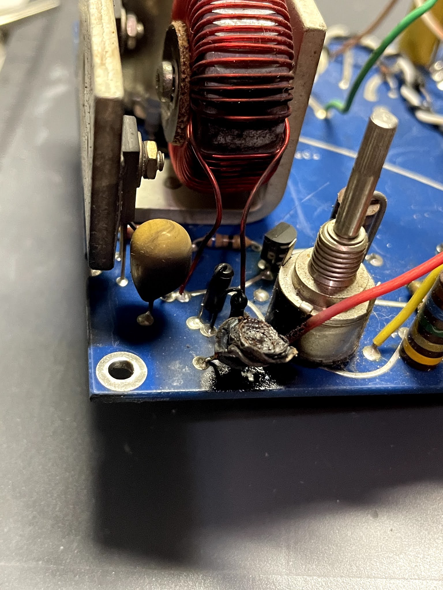
Since I believed the reason the test set was not working was because of the duty cycle regulator, I hooked up a 12v supply to the DC input of the back connector and bypassed the duty cycle regulator. Since it was a fused line and my power supply can regulate its own duty cycle I thought it would be ok.When I flipped the power switch, I quickly found the next bad tantalum capacitor. C46 on the 250KHz IF monitor Audio board caught on fire. See the image below.


IFR-1000s/Army version Service manual: http://www.rfstuff.com/manuals/IFR%201000S%20us%20army%20service%20manual.pdf


Comments
Post a Comment