IFR-1000S Restoration, First Mixer
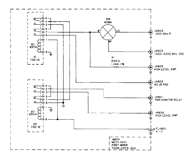
In working on the IFR-1000S Communications Service Monitor, I traced down what I believe to be one of the issues. The first mixer. The first mixer module is made up of a machined aluminum body, a MD-614 mixer, and two teledyne 732-12 RF relays. There are six ports on the module. none of them are labeled. I had to use the coax interconnect diagram in one of the service manual scans, and a frequency counter to figure it out. This lead me to find out my frequency counter actually can go up to 1.3GHz even thought its says 1GHz. which is good surprise. Below is a labeled diagram of the mixer ports and components.
I used a test signal through the antenna port from a signal generator to trace through the modules which lead me to the first mixer. The first mixer has no output on the J4804 on receive. On generate the coax which is normally connected to J4804 measures 1200MHz. The output of the 1200-2200MHz oscillator measure correctly, when the IFR is set to 50MHZ the output is 1250MHz. When set to 146MHz the output is 1346MHz. Both of the lock lights on the front of the IFR are lit up showing that the high frequency and low frequency signals have lock.
I need to replace this module and have a few sources I can try.


Comments
Post a Comment